Quick answer
An excavator hydraulic diagram is a symbol drawing of the oil path, from the pump through the control valve to the motors and cylinders and back to the tank. To read it, you identify the pump, valve, motor, and cylinder symbols, then trace the oil flow from the tank out and back again. Once you match the drawing to the real machine, you narrow down the failed branch before opening anything.
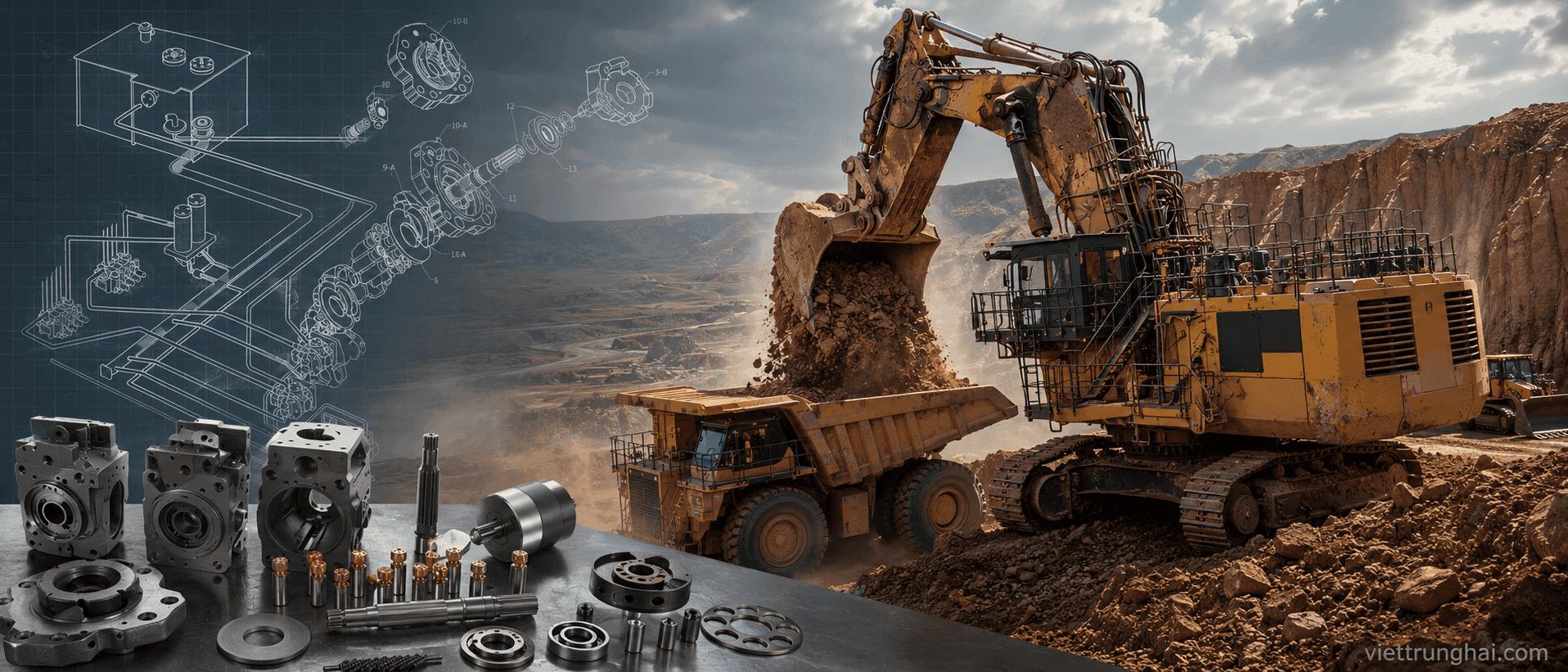
An excavator hydraulic diagram is a drawing that shows where the oil goes and how the parts connect, from the pump through the control valve to the motors and cylinders and back to the tank. Once you can read it, you stop guessing when the machine feels weak, runs hot, or loses power. You look at a symbol, trace the oil flow, then narrow down the suspect before you open anything. This guide walks through each group of symbols and how to use the diagram to diagnose, written the way an excavator repair technician would talk to a machine owner.
What is an excavator hydraulic diagram?
An excavator hydraulic diagram is a symbol drawing, not a photo of the real machine. Every part has an agreed symbol: pump, valve, motor, cylinder, filter, cooler. The straight lines between them are the oil lines. Reading the diagram means understanding where the oil starts, what it passes through, which valve controls it, and how it returns to the tank.
The drawing is like a road map. You do not need to memorise it, only to know how to look things up and follow along. Once you are used to it, a strange diagram from another model is still readable, because the symbols follow one common standard.
Why a technician should read the diagram before opening the machine
Opening a machine with no diagram in your head is like walking through a dark house. You take everything apart, clean it, put it back, and the fault is still there because you opened the wrong spot. The diagram lets you narrow it down: the fault sits in the pump branch, the valve branch, or the actuator branch.
It also helps you talk to the parts seller correctly. When you point at the regulator symbol and describe the symptom, the seller knows at once what you need. This saves time and avoids buying the wrong item. To grasp the whole picture first, review the hydraulic-system layout, then come back to reading the diagram.
The main blocks on a hydraulic circuit
An excavator hydraulic circuit always has four basic blocks. Remember these four and you can read any diagram. They are the pressure source, the control section, the actuator section, and the return section.
- Source: main pump, pilot pump, oil tank, filter.
- Control: main control valve, relief valves, pilot valves.
- Actuators: boom, arm, bucket cylinders; swing motor; travel motors.
- Return: tank line, cooler, return filter.
When you pick up a strange diagram, the first job is to mark out these four blocks. The rest is just detail inside each block.
Pump symbols on the diagram
A pump on the diagram is a circle with a triangular arrow pointing outward, showing the oil leaving. If the triangle is solid and points one way, it is a one-direction pump. Excavators usually use variable-displacement piston pumps, so the symbol has an extra diagonal arrow across the circle, meaning the flow is adjustable.
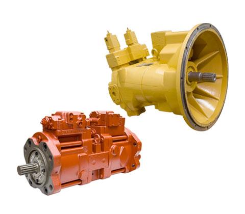
Most excavators use a tandem pump, so you will see two circles side by side sharing one shaft. Familiar pump families such as K3V and K5V are drawn this way. When the pump is weak, output is short, and the machine is slow and heavy on every motion. When it is time to change the internals, look at hydraulic rotary groups to pick the right block, pistons, and valve plate.
Pump regulator symbols
The regulator is the brain that controls the pump swash-plate angle to raise or lower flow. On the diagram, it is usually drawn as a small box attached to the pump body with pilot lines running to it. These lines carry pressure signals that tell the pump when to push more oil and when to pull back to spare the engine.
Reading this part carefully matters, because many weak-machine or high-consumption faults live here, not in the pump internals. If the signal line to the regulator is blocked or the spring is tired, the pump never reaches full flow. When replacing, look at pump regulators for the right model to keep the control character. Viet Trung Hai distributes JIC Hydraulics regulators, with precise machining and steady materials, so the character stays close to the original and lasts over time.
Main control valve symbols
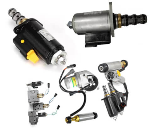
The main control valve is drawn as several squares set side by side. Each square is one spool position: hold, extend, retract. The arrows inside each square show which port connects to which at that position. When you move the lever, the spool shifts, moving from one square to another and changing the oil path.
This is the hardest part for beginners, but also the most important. To understand deeply how the spool splits oil to each function, read the main control valve. Once you are used to it, one look at a valve stack tells you which cylinder the oil is going to.
Relief and check valve symbols
A relief valve is drawn as a square box with a spring on one side and an arrow showing the drain path when pressure crosses the limit. It bleeds off oil to the tank to protect the system from overpressure. On the diagram, the main relief usually sits right after the pump or inside the valve stack.
A check valve is drawn as a ball resting on a seat, letting oil through one way and blocking the reverse. It keeps the bucket from dropping when you stop mid-motion. When a check valve leaks, the load sags slowly even with the lever back to centre. This is a clue you can read right off the diagram.
Hydraulic motor symbols
A motor is drawn like a pump but with the triangular arrow pointing inward, because the motor receives oil to create rotation. An excavator has a swing motor and two travel motors. Travel motors are usually two-speed, so the symbol has an extra pilot shift section.
When you read the motor branch, watch the counterbalance valve that goes with it. This valve keeps the upper structure from over-swinging on stop, and keeps the machine from drifting downhill. If the swing jerks or the machine drifts on a slope, trace this branch on the diagram first.
Hydraulic cylinder symbols
A cylinder is drawn as a rectangle with a piston rod sticking out one end. The two oil ports are on the two sides of the piston: pump oil into the base side and the rod extends, pump into the rod side and it retracts. An excavator has boom, arm, and bucket cylinders, sometimes an extra one.
On the diagram, you match which valve port connects to which cylinder port. When a cylinder is weak one way but normal the other, the likely cause is a leaking internal seal letting oil pass across the piston. The diagram helps you confirm the oil direction so you do not open the wrong part.
Line and pilot circuit symbols
There are two kinds of line on the diagram. A solid heavy line is the working oil line under high pressure. A dashed line is the pilot line, carrying low-pressure control signals. Telling these two apart is a key step, because many people trace the pilot line as the working line and get confused.
The pilot line draws oil from a separate pilot pump, through the control lever, to the two ends of the control-valve spool. When you move the lever, pilot oil pushes the spool. If pilot pressure is weak, the spool does not shift fully, and the machine works sluggishly even when the main pump is still good.
How do you trace the oil flow on the diagram?
The surest way is to follow the oil from the tank out and back to the tank. Start at the oil tank, through the suction filter, into the pump. From the pump, oil goes up to the control valve. Depending on the spool, oil branches into a cylinder or a motor. Once the work is done, oil comes back out, through the return filter and cooler, and back to the tank.
Use a finger or a pencil to trace each segment. Every time you meet a valve, ask what this valve does in its current position. When you finish one full loop, you understand the whole circuit. This habit keeps you from missing any branch during diagnosis.
Reading the pilot control circuit
The pilot circuit is small but it decides the control feel. It has the pilot pump, the pilot reducing valve, the left and right levers, and the travel pedals. From each lever, two pilot lines run to the two ends of a spool. Whichever side you push, the spool shifts that way.
Reading the pilot circuit helps you understand why the machine is sometimes heavy on the lever or slow to respond. The fault can be a tired pilot reducing valve, a worn control lever, or a leaking pilot line. These faults are not in the main pump, so without the diagram you easily blame the pump wrongly.
Reading a basic load-sensing circuit
Many newer excavators use a load-sensing circuit, where the pump adjusts flow to the real load. On the diagram, you see a small signal line taking pressure after the control valve back to the pump regulator. This line tells the pump whether the load is heavy or light.
Understanding this circuit keeps you from panicking when you see the pump swing flow up and down; that is normal design. When the load-sensing line is blocked, the pump reacts slowly and the machine jerks. A maker like Hitachi publishes diagrams and service documents for each machine family, so with the correct drawing for your model you can read the load-sensing circuit clearly.
Common hydraulic symbols table
The table below gathers the symbols you meet most when reading an excavator hydraulic diagram. Learn this table and you can already read most of the drawing.
| Symbol | Part | Quick meaning |
|---|---|---|
| Circle, triangle out | Pump | Creates pressurised flow |
| Circle, triangle in | Motor | Receives oil, makes rotation |
| Rectangle with rod | Cylinder | Pushes or pulls a load |
| Several squares, arrows | Control valve | Splits oil per function |
| Box with spring | Relief valve | Bleeds off on overpressure |
| Ball on seat | Check valve | Lets oil pass one way |
| Dashed line | Pilot line | Control signal |
| Solid triangle down | Oil tank | Where oil returns |
Matching the diagram to the real machine
Reading the diagram on paper is only half the job. The other half is going to the machine, finding the right valve stack and the right line the drawing names. You follow the colour and position of the lines, tracing from the pump out to match the diagram. Slow at first, but after a few times it becomes familiar.
When you can match paper to machine, your diagnosis gets much firmer. You no longer take things apart to try, but open exactly the spot you narrowed down. This is when the diagram repays the effort of learning to read it.
Using the diagram to diagnose weakness and pressure loss
When the whole machine is weak, you suspect the source: the pump or the main relief. On the diagram, the main relief sits right after the pump. If it bleeds early from a tired or dirty spring, pressure never builds and the whole machine is weak. This is the first check point on the drawing.
If only one motion is weak, you move to that motion's own branch: the spool, the anti-drift valve, or the cylinder. The diagram points you to the exact branch to measure. Thinking by branch narrows the fault fast, instead of feeling around the whole system.
Using the diagram to diagnose overheating
Abnormally hot oil usually comes from oil being forced through a tight gap and making heat. On the diagram, look for spots where oil can leak internally: a leaking relief, a passing cylinder seal, or a worn pump bleeding back to the tank. Each of these turns pressure energy into heat.
You also check the cooling branch on the diagram: cooler, fan, cooler bypass valve. If the bypass valve sticks open, oil skips the cooler and the machine warms up. Reading the diagram helps you tell heat from generation apart from heat from poor cooling.
Common mistakes when reading the diagram
The most common mistake is confusing the pilot line with the working line. Dashed and solid lines must be clearly distinguished from the start. The second mistake is forgetting that the spool has several positions; you must read the correct square for the motion in question.
The third mistake is skipping the small valves like counterbalance and anti-drift valves. They are small on the drawing but cause many drifting-load and jerking faults. Reading each symbol carefully, not skimming, is how you avoid these three mistakes.
Choosing the right parts after reading the diagram
Once the diagram points to the failed part, the next step is choosing the correct replacement. Being able to read the drawing helps you describe exactly what you need, avoiding the wrong model or the wrong assembly. Look at the hydraulic-pump parts group to match pump, internals, and regulator to your machine family.
On quality, Viet Trung Hai favours JIC Hydraulics for pumps, rotary groups, valves, and regulators, because the materials and machining precision are steady, with a clear warranty. For cylinder seals, PET Seals is a durable, tight choice. Against loose aftermarket stock, these brands keep a character close to genuine at a more reasonable cost.
Safety notes when checking against the diagram
Before opening any oil line, bleed off all residual pressure in the system. High-pressure oil escaping can cause serious injury. The diagram shows where pressure is still held, such as an accumulator or the line after a check valve, so you can bleed the right spot.
Always lower the boom and bucket to the ground and shut off the engine before opening. Never search for a leak with a bare hand on a high-pressure line. Read the diagram to predict where the oil will go when you open a given port.
Do you need any tools to read the diagram?
You only need the correct drawing for your model, a pencil to trace the oil flow, and a pressure gauge when you go to the real machine. The correct drawing matters most, because the same model in a different year can have a different circuit. A wrong drawing turns correct reading into a wrong result.
When you need to measure for confirmation, fit the gauge to the test port the diagram indicates. Combining the drawing with real measurements gives you a firm conclusion. That is how a good technician works: read, then measure, then conclude.
If you need a pump, rotary group, or regulator to replace on your machine, message Viet Trung Hai with the model and the symptom; we advise the right item based on your diagram.
Key takeaways
- An excavator hydraulic diagram is a symbol drawing, not a photo of the real machine.
- Remember four blocks: source, control, actuators, and return to read any drawing.
- A pump arrow points out, a motor arrow points in; solid lines are working, dashed are pilot.
- Trace the oil flow from the tank out and back so you miss no branch.
- Use the diagram to narrow weakness, pressure loss, or overheating before opening parts.
- Read first, measure pressure at the right port next, then conclude and choose parts.
Written by
Trần Quốc Bảo
Trần Quốc Bảo works on hydraulic pumps and rotary groups at the Việt Trung Hải workshop. He measures pressure, overhauls and load-tests pumps across many excavator generations, and writes about pump principles, K3V rotary groups and fixing weak pumps from real cases.
Related parts
The exact parts discussed above — send your machine model or pump code to match.