Quick answer
On an excavator, the types of hydraulic valves fall into six main groups: the main control valve, relief valves, check and pilot-operated check valves, throttle valves, solenoid–pilot valves, and counterbalance valves. Each one routes oil, caps pressure, holds load, meters speed, or locks a cylinder at rest. Reading the right group and its telltale failure signature lets you isolate a fault fast, instead of pulling the whole valve block just because the machine feels weak.
On an excavator, oil travelling from the pump to the cylinders and motors always passes through several layers of valves, and the types of hydraulic valves doing this work fall into six main groups: the main control valve, relief valves, check valves, throttle valves, solenoid–pilot valves, and counterbalance valves. Each group has one job — routing oil, capping pressure, holding load, metering speed, or locking a cylinder at rest. Knowing which group you are looking at, and its telltale failure signature, lets a mechanic isolate a fault fast instead of pulling the whole valve block just because the machine feels weak.
What are the main types of hydraulic valves?
The main types of hydraulic valves on an excavator fall into six groups: the main control valve, relief valves, check valves, throttle valves, solenoid–pilot valves, and counterbalance valves — while a weak machine, drifting boom, or slow bucket are only symptoms, not causes. The same complaint that "the machine can't do the work" can come from a relief valve stuck open, a worn main control spool, or a leaking pilot-operated check valve. Without grouping the valves in your head, it is easy to jump straight to pulling the pump or swapping the entire valve block — expensive, and often the wrong target.
The right way to think is to follow the oil. The pump makes flow; the relief valve sets the pressure ceiling for the whole system; the main control valve decides which cylinder the oil reaches; check and counterbalance valves keep the load from dropping; throttle and solenoid–pilot valves fine-tune speed and the order of movements. A failure at each link leaves a different "signature" on how the machine behaves. Reading that signature is half the way to the answer. This article sits within the broader hydraulic system knowledge set and digs into each valve family and how to recognise them in the field.
The six valve groups and where they sit in the circuit
Before the detail, put them on one diagram. The table below summarises each group's function, its typical position in the circuit, and the failure sign the operator usually notices first.
| Valve group | Main function | Position in circuit | Common failure sign |
|---|---|---|---|
| Main control valve | Routes oil to each cylinder/motor | Central valve block, after the pump | One slow movement, cross-load, judder |
| Relief valve | Sets pressure ceiling, dumps oil on overpressure | Inside the control block and at ports | Whole machine weak, can't lift the load |
| Check / pilot-operated check | Passes oil one way, holds load | Cylinder return line, boom/arm base | Boom drifts down while the lever is held |
| Throttle (flow control) | Restricts flow, sets speed | Secondary branches, pilot circuit | Movement too fast or too sluggish, no smoothness |
| Solenoid–pilot valve | Switches by electricity, supplies pilot oil | Spool ends, control unit | No sub-gear, lost function, electrical fault |
| Counterbalance valve | Holds heavy load, stops load runaway on lowering | Boom/arm cylinder ports | Lowering surges or judders, loss of control |
These six overlap in duty. A modern main control block usually integrates the main relief, port reliefs, anti-cavitation check valves, and sometimes counterbalance valves as well — so "changing a valve" on an excavator is rarely swapping a single part. Understanding the functional boundaries helps you read the schematic and order the right hydraulic valve parts.
Main control valve — the heart that routes the oil
The main control valve is the large valve block sitting right behind the main pump. Inside are spools that slide back and forth in the valve body. When the operator moves a lever, pilot oil shifts the spool, opening a path for the main oil to reach the boom, arm, bucket cylinders, or the swing and travel motors. Each spool handles one movement; all of them share one cast body that splits and combines the oil flow.
Position and mechanism
The spool and bore are a precision-fitted pair, with a very small clearance so oil cannot slip past when the valve is closed. That clearance is the weak point over time: abrasive particles in the oil wear the spool edges and the bore, opening the gap. Oil begins to leak internally — flowing around rather than fully reaching the cylinder. Each spool section also has a centring spring that returns it to neutral when the lever is released; a weak or sticking spring keeps the spool from returning to its true centre.
The failure sign the operator notices
The classic signature of a worn control valve is one movement that is markedly weaker or slower than the rest, while the rest of the machine stays strong. That is because internal leakage only happens in the worn spool section. Sometimes you see "cross-load": while curling the arm, the boom rises slightly on its own because oil leaks into the neighbouring section. A spool sticking on dirt tends to feel jerky — the movement engages late, then jumps. To understand this unit's construction and its own checks, see the article on the main control valve.
Relief valves — the pressure ceiling
The relief valve sets the system's pressure limit. When circuit pressure reaches the set point, the valve opens and dumps oil back to tank, preventing pressure from climbing further and cracking hoses, blowing seals, or damaging the pump. An excavator has a main relief for the whole system and port reliefs that individually protect each cylinder line from shock loads — for example when the bucket strikes hard rock.
How it opens and closes
Inside is a ball or piston pressed onto a seat and held there by a spring. Oil pressure pushes back against the spring; when the oil force beats the set spring force, the valve cracks open and bleeds off. The seat and seating face must close absolutely tight — a single scratch or a trapped particle there lets oil leak past continuously. A pilot-operated relief uses a small valve to control a larger one, reacting more smoothly but also more sensitive to dirt.
When the relief sticks open: the whole machine goes weak
This is the easiest signature to read. If the main relief sticks slightly open, or its seat is scored, oil dumps back to tank before pressure can even build. The result: every movement is weak, the machine can't lift its load even though the pump keeps turning normally, and the oil tends to heat up fast because pump energy is wasted as heat. Conversely, if the valve sticks shut or is set too high, the system loses its protective layer and can spike pressure enough to blow seals. A failed port relief usually shows up in one specific direction — a single movement weak or shuddering under heavy load. The mechanism and adjustment are dissected in the article on the hydraulic relief valve. Note too that unstable pressure can trace back to an accumulator in the control circuit that has lost its gas charge, so when diagnosing wandering pressure, look at that unit as well.
Check and pilot-operated check valves — holding the load
A check valve passes oil one way and blocks the reverse — simply a ball or disc on a spring seat. In the excavator circuit, anti-cavitation check valves refill a cylinder when the load pulls the piston faster than the pump can supply, avoiding a vacuum that forms air bubbles.
The pilot-operated check and boom drift
More important for holding load is the pilot-operated check valve. It locks oil in the cylinder chamber so the boom stays put when the operator lets go, yet can be opened by a pilot signal when you want to lower. Thanks to it, the boom and bucket do not sag under their own weight.
The failure signature is very clear: when the pilot-operated check or its related seals leak, the boom drifts down slowly even though the operator holds the lever in neutral. It drifts faster with heavier load and hotter oil (thinner oil leaks more easily). You must separate drift caused by the holding valve from drift caused by a worn control spool — the difference lies in isolating each section of the circuit when you test. The full principle is in the article on the hydraulic check valve.
Throttle valves — setting speed and keeping it smooth
A throttle (flow control) valve narrows the flow cross-section to restrict how much oil passes through a branch, thereby adjusting movement speed and smoothing the start and end of a stroke. On an excavator, throttling appears often in the pilot circuit and in secondary control lines, where the movement needs a smooth rhythm rather than a jerk.
A throttle can be fixed or adjustable; the pressure-compensated type keeps speed steady even as load changes. The throttle orifice is small, so it is very sensitive to dirt: one trapped particle chokes it and the movement turns sluggish; conversely, if the orifice is worn wide or the wrong size is fitted, flow passes too freely and the movement jerks and loses smoothness. When one function suddenly changes character — faster or slower than normal while system pressure stays fine — think of the throttle and the pilot line before blaming the pump.
Solenoid and pilot valves — the bridge between electricity and oil
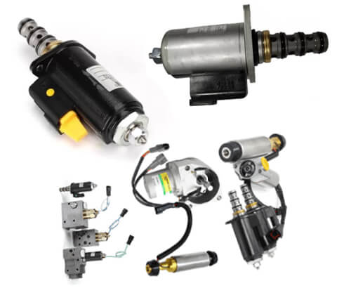
The solenoid valve is where the electrical signal meets the oil flow. The coil is energised, its magnetic field pulls the valve core, and it opens or switches the pilot oil path. That pilot oil is the force that then shifts the main control spool or triggers functions such as travel-speed sub-gear, safety lock, or a dig-mode change. Pilot valves also include the joystick pilot unit, which turns lever force into a proportional control pressure.
The failure signatures here carry both an electrical and a hydraulic flavour. A broken or shorted coil kills one function outright — no high-speed travel, say, or a mechanism that will not respond even though the lever moves. A core stuck on dirt makes a function work intermittently. If the pilot line is low on pressure — from a worn pilot pump, a clogged pilot filter, or a leak — every movement becomes heavy and slow to engage, because the main spool has too little force to shift it. For "flickering with temperature" or "one function lost" faults, measure coil resistance and check pilot pressure before opening the main valve block. Referring to valve technical literature from a manufacturer such as Bosch Rexroth helps you cross-check symbols and standard circuit diagrams.
Counterbalance valves — holding heavy load and stopping runaway
The counterbalance (holding) valve sits at the load-bearing cylinder port, usually the main boom and the arm. Its role has two parts: holding the load still when no one is operating, and creating back-pressure on lowering so the load does not run down faster than the pump supplies. That makes the lowering movement smooth and controlled, even when the boom is reaching far with a heavy load.
When a counterbalance valve fails, the signature is fairly distinctive. A weak spring or a leaking seat lets the load sag or surge the moment you crack it open to lower — a "sinking" feeling followed by a jerk. Dirt sticking in the reverse direction makes lowering judder with an uneven rhythm. Because the counterbalance valve and the pilot-operated check both deal with holding load, they are easy to confuse when diagnosing; the distinguishing point is that the counterbalance valve also governs the feel of lowering the load, not just holding it still.
Failure-sign cross-reference by valve group
The six-group table above already pairs each valve with the failure sign it most often shows, so when you narrow a fault down, work backwards from the symptom the operator reports to the right group. A whole machine that is weak and can't lift the load usually means the main relief valve is stuck open, dumping oil early to tank. One movement slow or weak while the rest stay strong is internal leakage from a worn spool clearance in the main control valve. A held lever with the load still drifting down is a pilot-operated check leaking at its seat and failing to lock the oil. Lowering that runs away or judders is a counterbalance valve with a weak spring and lost back-pressure. One function lost together with an electrical fault is a solenoid–pilot valve with a broken or shorted coil or a stuck core. And a movement that suddenly turns too fast or too sluggish is a throttle orifice choked or worn wide. This cross-reference is only a starting point for narrowing things down. On a real machine, several valves share one block, so the confirmation step always means isolating each circuit section and measuring pressure at the right port, rather than guessing from a single symptom.
How to recognise them quickly in the field
Shape and position are the first clue. The big, heavy unit with many levers and many pipes converging on it is the main control valve. The hex-head plugs with a spring inside, adjustable by turning, are usually relief valves. The cylindrical body with a coil and an electrical connector is the solenoid valve. A valve bolted right at the boom/arm cylinder port, a compact block clamped between the pipe and the cylinder body, is usually a counterbalance or pilot-operated check valve.
Once recognised, let the machine's behaviour guide you in a sensible order:
- Decide whether the symptom is global (whole machine weak) or local (one movement) — global points to the main relief and pilot circuit, local points to the spool or the holding valve of that branch.
- Test for drift while a held load stays still, to separate the load-holding group (pilot-operated check, counterbalance) from the routing group.
- For lost-function or temperature-flickering faults, measure electrical values and pilot pressure before opening the main valve block.
- Only pull a valve unit after you have isolated the suspect circuit section; pulling the whole block blindly wastes labour and easily introduces dirt into the system.
How to choose the right type and replacement spec is covered in the article on choosing a hydraulic valve, worth reading alongside this before you order.
Choosing a replacement valve: material, machining, durability
A hydraulic valve lives on the tightness and precision of its fitted pair. For the main control valve, the spool–bore pair must be concentric and smooth, with tight tolerance to limit internal leakage; the spool steel needs a case-hardened surface to resist wear. For relief and counterbalance valves, the seat and seating face must be hard and finely machined to close tight for the long term; the spring must hold its set force over time and not fatigue early. Seals and rubber seats need the right material so they neither swell nor harden with oil and heat.
In this parts group we put JIC Hydraulics (the phu tung bom thuy luc JIC / Axion line) first as the standard replacement. JIC valves and valve cartridges are made to the correct part number, material, and tolerance of the original unit, so they fit straight, seal well, and hold up through many heavy-load cycles — decisive for a part where a single small clearance already causes a leak. Product-line details and type cross-references are on the JIC Hydraulics site. After JIC, depending on the machine and stock, there are other quality imported options; the general rule is still to prioritise the correct part number and machining quality over the lowest price, because a cheap valve that leaks early drags oil temperature up and wears the pump too.
When you need a full unit or a valve cartridge with seals, consult the hydraulic pump parts catalogue to source everything in one order, avoiding the case where you fit a new valve but the old seal still leaks.
When to replace and when to recondition
Not every failed valve means replacing the whole unit. A lightly scored relief seat can sometimes be lapped back if the mark is not deep; a solenoid valve that has lost function may only need its coil or connector, and swapping just that part is enough. A worn control spool and bore are different — once internal leakage from wear has set in, restoring the original clearance is very hard, and you usually replace the fitted pair or the whole section.
A practical rule: repair what you can isolate and for which a standard loose part exists; replace when the precision fitted pair is worn, or when the cost of reconditioning approaches the price of a new standard-quality unit. And always tackle the root cause — dirty oil — in parallel, because most early valve failures are the result of contaminated oil, a clogged filter, and water in the oil, not of a poor valve itself. Changing a valve without cleaning the system is just buying one more failure.
Key takeaways
- An excavator hydraulic system has six main valve groups: main control, relief, check, throttle, solenoid–pilot and counterbalance.
- Weakness across the whole machine points to a main relief stuck open, while one weak movement points to a worn control spool.
- A boom that drifts down with the lever in neutral is the signature of a leaking pilot-operated check or holding seal.
- Runaway or juddering on lowering usually means the counterbalance valve lost back-pressure, while a lost function with an electrical fault is the solenoid.
- Diagnose by following the oil and isolating each circuit section, rather than pulling the whole block blindly and letting dirt in.
- Choose a replacement to the correct part number and machining, JIC Hydraulics first, because a single small clearance is enough to leak and wear the pump.
Written by
Trần Quốc Bảo
Trần Quốc Bảo works on hydraulic pumps and rotary groups at the Việt Trung Hải workshop. He measures pressure, overhauls and load-tests pumps across many excavator generations, and writes about pump principles, K3V rotary groups and fixing weak pumps from real cases.
Related parts
The exact parts discussed above — send your machine model or pump code to match.